|
|
Theatre Clock Projectby Cathy Saxton The ProjectOur local theatre contacted us to see if we could help with controlling the accelerated movement of a clock's hands during a scene in an upcoming production. They had been working on this, but hadn't yet been able to create a system that worked reliably. The small DC motor they had been using would just whine when a low voltage was applied, then start spinning wildly once it got enough voltage. We proposed using a stepper motor. Steppers work great for tasks where a specific angle needs to be moved, and I had experience with controlling them from a previous robotics project. By the time we got involved, it was just a few days (mostly over a weekend) before "tech" needed to be complete. This added additional challenge to the project since not only did we need to create a final working product in just a few days, we could only use parts that we had or could get locally (no time for mail order). Fortunately, we had several stepper motors and various other parts that we knew would be necessary for the project, so we dove right in! Note: enable JavaScript in your browser to expose an option for showing technical details in the sections below! Additional technical details will appear in the sections below. They will appear in this format, indented with a teal bar on the left. Getting StartedThere were two basic things to do: (1) demonstrate a stepper motor moving a specified amount, and (2) figure out how to get notification from the theatre's control system when it's time to run the motor.
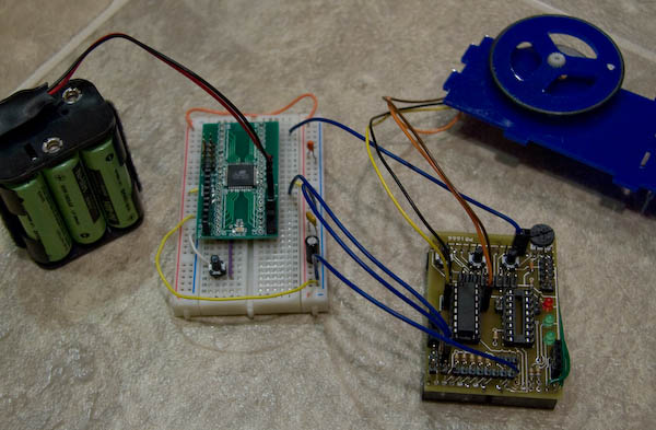
Running the stepper motorGetting a stepper rotating was pretty easy. I had the necessary parts in my stash and wired up a circuit. For the software, I wrote some simple code to spin the motor when a button was pressed. The picture below shows this test setup. Next to the batteries (on the left) is a
breadboard which has a controller (the brains; this is what runs my program) and the
pushbutton that starts the motor running. In the lower right of the picture is a board
that I had from a prior robot project. Most of the contents of that board are
irrelevant for this project, but it was a useful way to connect to the chip that
helps control the stepper motor. That board gets power and control signals via the blue wires.
The other four wires connect to the motor. Mounted on the motor is a wheel that has
a silver dot to make it easy to track motion when it spins. For MCUs, I like using the Atmel AVR series. The green PCB in the breadboard is a custom board that I designed a while ago. It has an ATmega644 and a voltage regulator (plus a power switch, power-indicator LED, and headers for programming and serial I/O). All of the MCU's pins are available on the breadboard, plus regulated and battery power. The breadboard has a variety of capacitors to help keep the voltage stable. The yellow-brown PCB is also a custom board, designed when I was building a robot that used stepper motors. It doesn't have a solder mask over it, which is why its coloring is different. The IC you can see in the photo is a stepper motor driver. It takes care of sending the appropriate sequence of power and ground signals to each of the coils in the motor. To control it, I just need to pulse a clock line. Another input line indicates whether to rotate clockwise or counterclockwise. The unpopulated DIP socket on the right side is for another stepper driver IC since the robot had two motors. The software waits for a press of the button, then outputs pulses to have the motor spin. I wanted an easy way to be able to show different speeds and numbers of steps without having to change parameters and recompile, so I ended up outputting different pulses on several lines. The wire connected to the breadboard PCB's upper right pin is the clock input to the stepper driver. I could connect it to any of the first four pins to show different speeds and angles of rotation. The motor is a small stepper that I got for a robotics project several years ago. At that time, I got it running with a setup similar to this one, spinning the wheels in the air. Unfortunately, when I put the weight of the robot on the wheels, the motors weren't powerful enough to move the robot; disappointing considering that its weight was primarily comprised of the motors and some batteries. So, one concern that we had about this was whether the motor would be powerful enough to move the clock mechanism and hands. The motors I got to replace these in the robot are much larger, heavier, and noisier when running, but were also available for this project if necessary. I got the stepper surplus somewhere, so I'm not sure about its specs. It seems OK running at 7.2 V, which is the minimum that the stepper driver allows, so that's what we're using. The one downside of this motor is that there are just 20 steps per revolution. The larger ones are 200 steps, but their considerable noise and weight made them less appealing for this project. Once we had the sample motor demo working, we showed it to the theatre staff. They seemed excited by its potential! We got a chance to see the clock mechanism at this point and were pleased to see that it was small and that the hands were very lightweight. I figured that the small, lightweight stepper motor would be able to handle it without any problems. We left a motor with the theatre crew so they could mount it to the mechanism (along with another gearing stage). We still had the second one to use for testing at home. Interfacing with the control systemThe theatre's lighting system, in addition to controlling brightness levels, colors, and movements of lights, also triggers a wide variety of other actions, such as running motors to move scenery. The clock mechanism needs to get its cue from this system. From conversations with theatre staff, we knew that the light board communicates via "DMX," but we weren't familiar with that protocol. We discussed options with them and decided that the simplest plan would likely be to use an existing LED-control module designed to work with the lighting control system. The module would handle receiving the DMX communications and detecting the appropriate triggers from the light board, and we'd watch the module's outputs to determine when to run the motor. We hooked up the output from the LED module to an oscilloscope to determine what its output looked like. Unfortunately, it wasn't at all what we expected. After a couple hours of experiments and head-scratching, Tom finally suggested that we should abandon the LED module plan and just listen to the lighting board signal directly. I realized that was an excellent idea, so Tom did some research on that system and we both took a little break to watch some of the rehearsals. The LED module is designed to control red, green, and blue LEDs in a strip, reportedly outputting up to 12 V based on the level specified by the light board. We expected that for dimmed values this wouldn't actually be a steady voltage level, but would be a PWM signal -- a pulse from 0 to 12 V with a duty cycle corresponding to the desired brightness level. We had also expected to be able to use one of the colors to provide power to our board and then use the other two colors as triggers. The output was nothing like the square wave we expected, and not conducive to being used as an input trigger. We also had problems with the plan to use one color as power. The three LED outputs share a common power, and asking for an LED to be fully on gave us the expected 12V drop to that color's output, providing what we intended to use as ground. But, we were unable to reliably measure voltage between this "ground" and the other color outputs. We experimented with pull-up and pull-down resistors to no avail. This process was of course an ongoing series of attempts to understand or overcome a problem, with the answer appearing to be just within reach. I became so engrossed in this process that I needed Tom's outside observation to break me out of the cycle of trying just one more thing! The reality was that there were too many problems and we really didn't have any solutions. Tom found some good information on the DMX protocol and we decided that we'd be able to handle listening to the light board directly, so we officially abandoned the LED-module plan. Our next step involved some more work at home, so we borrowed a device that sends a signal that we could use to test our DMX-listening code. Revised plan for interfacing with the control systemThe data sent from the light board turns out to be very easy to interpret. The issue was that the signal is at a voltage that is outside the range that our controller can handle. As you might imagine, there are chips that can do the conversion; there are a wide variety available online, but it's not a common enough consumer-level part to be carried at local retailers. We needed this on a Saturday, which effectively ruled out mail-order. The DMX protocol runs on an RS-485 bus, which has three signal wires: ground, DATA+, and DATA-. The two data lines basically mirror each other as something like +1.5V and -1.5V, with a '1' indicated by DATA+ higher than DATA-, and a '0' for the flip state. The MCU can't tolerate negative voltages, so can't read the data lines directly. Standard RS-485 transceivers do the conversion, so would be the ideal solution. We looked online to see if we could get an RS-485 transceiver locally at Vetco, Supertronix, Fry's, or Radio Shack, but couldn't find one. Local friends also didn't have any. I asked for advice from friends in an online robotics chat, and got a suggestion from Richard for a solution for which I had parts. I was quite elated, as the main component was something I had purchased because it seemed like a useful part to have on hand! Richard suggested using an op amp and also provided information on the resistors to use in that circuit. We wired this circuit on a breadboard and tested it; it seemed to work fine. We had now done proof-of-concept tests for all the parts of this project and were ready to build the final device. Building our DeviceHardwareI made a list of all the items that needed to be on the board, then planned out where to put things on a perf board. I even had a little extra room for some LEDs and a button; they are useful for testing. After I had a layout, I started soldering. I used EAGLE CAD to enter the schematic and also to lay out the board. Even for perf boards I'll be wiring manually, it helps me visualize the component placements and connections. (I don't bother routing traces, but do use the "air wires" to identify connections that will need to be made.) SoftwareGetting Messages from the Light BoardWhile I was working on soldering the board, Tom researched the DMX protocol and wrote code to interpret the DMX communication, watching for the "channels" that convey the triggers to which we need to respond. His code collects and stores the values for our channels, then supplies those values to the code that runs the motor. It turns out that the DMX protocol is fairly straightforward: the input is idle high, a low on the line for a minimum specified period indicates the start of a packet, which is followed by a string of 512 bytes, one for each channel. Format is 1 low start bit, 8 bits of data, then 2 high stop bits. The MCU has built-in support for serial communications. After setting up the USART to indicate the baud rate, number of bits, etc, we can just instruct the MCU to watch for data. It watches the input line and provides notification when a full byte has been received. But, we have to detect the low start-of-packet signal manually and then wait for the transition back to high before asking the USART to receive bytes. And of course, we need to ensure that we've seen the low signal for a long enough period to indicate that it's the start of a packet. Tom's code watches for the signal that a packet is starting, asks the USART to start receiving, counts bytes until the first channel in our series, then caches the received values in an array. At that point, we stop watching the DMX bus and execute the code to run the motor. When that is done, we go back to watching the bus, waiting for the start-of-packet signal. One challenge with receiving the DMX signal is that it is sending data very quickly relative to the speed at which the controller runs. It was an interesting problem to make sure that the code was fast enough to handle all the issues that arise as a result of this. The DMX bus runs at a zippy 250 kHz, so the whole 512-byte sequence can be sent over 40 times per second. This is why we don't bother watching while we're running the motor; as soon as we're done with the motor and ready to process another command, we'll get another packet nearly immediately. When we need to time something (e.g. the low signal), we typically use one of the MCU's counters: we record the beginning state, loop until the terminating condition is satisfied, then look up the current counter value and calculate the elapsed time. The counter runs at a steady rate, so this is a convenient, reliable way to measure time. In the case of timing the duration of the low input from DMX, we were concerned about the number of MCU clock cycles that this process would take. Once the end condition is detected, we have just two bits before the data is allowed to start. For a 250 kHz signal processed by an 8 MHz MCU, that's just 64 clock cycles. In that short time, we need to detect the input's change to a high state, exit the loop, read the current counter bytes, calculate the corresponding elapsed time, compare it to the required minimum, and start watching for bytes if we saw the low input for long enough. We realized that the data transmission could start before we were ready if we waited until the signal had transitioned to high before spending the time to calculate the duration of the low signal we'd seen. So, we decided to do the timing check during the low period. This meant that the instructions required to check the counter and calculate elapsed time happened before we got to the short two-bit period before data starts, leaving us plenty of time to get ready to receive data. When testing this code, we found that we correctly picked up the values on the channels we were watching, but we also erroneously picked up values from other channels, acting as if these were our channels. Much head-scratching and thrashing on code ensued. We finally realized exactly what was causing this problem, but still needed to devise a solution. We eventually hooked up the oscilloscope to see what was happening. That didn't really shed much light since it looked as we expected, but in discussing our observations, we had a revelation: during the low period, we were spending so many clock cycles checking the counter and calculating elapsed time (in addition to watching for a high signal) that we missed the brief high stop-bit period between sequences of 0 values; this caused us to believe that the low period had continued uninterrupted, which could cause us to falsely detect a start-of-packet signal. This meant that we would randomly start reading in the middle of the channel sequence. So, we found ourselves once again considering how to minimize the clock cycles spent detecting and reacting to the low start-of-packet signal. Our current code made sure that we could react quickly when the signal transitioned to high, but in return it caused us to spend too much time distracted during the low period. At this point we went to get dinner, because I always think better when I'm not hungry! That worked quite well: by the end of dinner we had a plan. A little more work in the code, and things appeared to be working better. We concluded that we had to minimize our activities during the low period while watching for the transition to high. That meant deferring the check of elapsed time until the high was detected. This of course brought us back to the original issue of having so few clock cycles before the data started. Fortunately, we came up with two solutions to this. Our first change was to tell the MCU to start receiving serial data as soon as we detect the high input. This ensures that we don't miss any data. We then have the duration of the first byte (which is conveyed in 11 bits -- 1 start + 8 data + 2 stop) to check to see whether we saw the low input for long enough to indicate that we've got the start of a new DMX packet. If it was too short a time, we just turn off the MCU receiver and go back to looking for a long low input. With this change alone, it is possible that we would have had enough time to check a counter and calculate elapsed time, but it seemed like we were still running the risk of taking too long, so we decided that we should also speed up the calculation of how much time had elapsed during the low signal. So, our second optimization was to time using MCU clock cycles. This can be a risky strategy since any interrupts that happen will not be accounted for, and you can't count clock cycles directly from C++ code. In this case, we have disabled interrupts, and we can look at the generated assembly code to see exactly how the compiler translated our C++ code to machine code. During the low period, we loop to check the input pin and simply increment a counter each time through the loop. We can look at the compiled code to see the assembly instructions executed while in the loop, then calculate how many clock cycles are used for each iteration. Since interrupts are disabled when this code is running, we have a very accurate measure of the amount of time we spent in the loop. Once we see the transition, it's just a simple compare to see if we've looped enough times. The code uses a 32-bit variable to count iterations of the loop. (A 16-bit variable would wrap back to 0 after just 41 ms.) The input signal is checked by looking at the low bit (bit 0) in register PIND. This is the C++ code:
ulong c = 0;
while (!(PIND & 0x01))
	++c;
This is the assembly code generated (with our comments added for explanation here):
ldi  r24, 0x00 ; initialize counter variable to 0
ldi  r25, 0x00
ldi  r26, 0x00
ldi  r27, 0x00
rjmp .+6       ; jump to check (sbis)

               ; the following instructions are executed
               ; each time through the loop

adiw r24, 0x01 ; increment of 2 low bytes of 4-byte counter
adc  r26, r1   ; handle carry to upper bytes from increment
adc  r27, r1
sbis 0x10, 0   ; skip next inst. if D0 is set (exit loop)
rjmp .-10      ; loop to check again
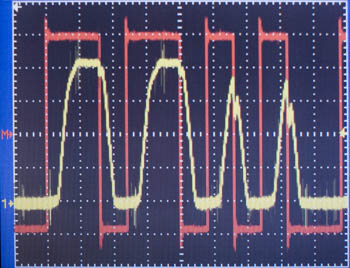
The Knowing how many clock cycles are used each time through the loop (7), we can calculate the number of loops corresponding to the minimum time required to indicate that a new packet is starting. Here's the final result of the code speed-up: When a low signal is detected, we enter the 7-clock-cycle loop that watches for the transition to high and counts iterations of the loop. This is fast enough that we won't miss the brief high stop-bit pulses between 0-value channel values. Once the signal goes high, we start the USART so it can catch any data that appears. After starting the USART, we check to see if the low signal was a long enough duration to indicate the start of a packet. This is a simple comparison of the loop count with a pre-determined minimum number of loops required (based on the MCU clock speed and the clock cycles per loop). If the low was long enough, we start processing the bytes collected by the USART. If not, we just turn off the USART (no harm done in running it briefly and ignoring anything it might have seen) and start watching for another low signal. Running the MotorThe demonstration code used a somewhat brute-force approach to generate the signal that goes to the chip that controls the stepper motor. I decided to make the code a bit more robust and flexible, so I re-wrote the main part of the motor-movement code. The new code uses a feature of the controller that I've used many times before, so creating the code was a fairly quick, but this did of course mean that I had new code that needed to be tested. The motor rotates one step each time the clock input to the stepper motor driver goes high. I set up the 16-bit timer/counter to toggle the output line (OC1A) when the counter value reaches a specified value. Changing that target value controls the speed of the rotation. (I knew I wanted to make this change, so I took this into account when designing the board and made sure that the clock input to the stepper driver was coming from one of the counter output pins.) The motor rotation code looks at values from three channels. It uses values on the "clockwise" and "counterclockwise" channels as the number of steps to make (which correlates to a distance to move), and the value on the "speed" channel sets the rate at which the movement happens. Testing and TroubleshootingSince the DMX testing device we'd borrowed was easiest to use with low channels, we set our code to collect values starting at channel 1. We tried running clockwise and counterclockwise at various speeds, and things seemed to work great. But, we were getting indications (via the LEDs) that sometimes errors were detected when reading the DMX data. Of even more concern, watching for data at channel 200 was very unreliable, and we got communication errors consistently. Our assigned channel was over 200, so this presented a problem. We had one of the LEDs set up to indicate frame errors. It would flicker a bit when we used low channels, but was on nearly solid when we were trying to read from high channels. We spent quite a bit of time trying to track down this problem. We both looked at code and tried many experiments to diagnose what was happening. Tom finally requested that we hook the circuit up to the oscilloscope to see what the signal looked like. Here is an oscilloscope reading of the original signal (red) and the corresponding output
from our conversion circuit (yellow). The slight shift isn't a problem, but the shape of the
waves is. In our circuit, the transitions between high and low are not instantaneous, and
shorter pulses don't achieve full voltage before dropping back to zero. This "sloppy"
wave means that the controller sees high values for a shorter time (50-75% of the original),
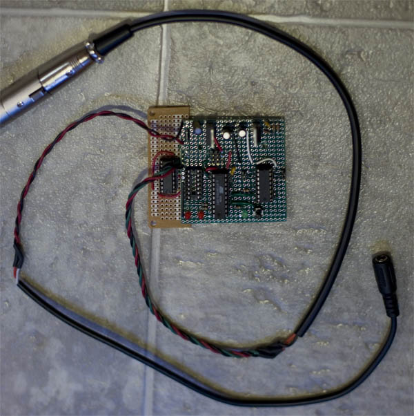
which ends up corrupting the data. The red trace is the RS-485 signal; it's a calculation of DATA+ minus DATA-. The yellow trace is the output of the op amp. Indicators on the left side show the 0 mark for each trace. Vertical scale is 1 V per gridline; horizontal is 5 μs. The spec sheet for the ATtiny2313 shows that when powered at 5V, it will transition to high at around 3 V, then back to low around 1.5 V (inputs have hysteresis). The MCU's USART will sample the wave several times per bit, so the slow rise time may cause it to erroneously conclude that a bit is 0 when 1 is intended, and also to adjust its interpretation of when a frame starts. This error accumulates as bytes go by and we get frame errors after a number of bytes. It was clear that we truly needed the right part for this job, that our replacement circuit, while seeming to work in simple cases, was not up to the task. By this time, is was Monday evening, too late to order for overnight delivery on Tuesday, and our deadline was Tuesday at 2:00. We considered asking the theatre whether we could get a different (low-number) channel assignment, but were unhappy with the fact that our device was clearly not working correctly. Revising the HardwareI returned to the online robotics chat and got more advice. David suggested a part that was designed to do the voltage conversion we needed. It's not the specialized chip that I originally looked for, but is an appropriate tool for this job. I found a local electronic store that indicated they had it in stock. Tom planned to get up early the next morning to arrive there when they opened. I proposed waiting until we could call and confirm that they actually had it, but Tom wanted to give me maximal time with the part and the store was 30 minutes away. Of course, Tom got there and the peg was empty. Turns out there's a little notice on the site that mentioned that they don't actually have the parts they're showing, they're just in hundreds of warehouses around the country. Gee, that's useful... Fortunately, Tom noticed that the parts were grouped by functionality, so he read me part numbers from nearby pegs. I looked up spec sheets and was delighted to find a couple that looked like they would work; Tom got them both. While Tom was driving home, I looked at the spec sheets in more detail and selected the part I wanted to use. Both of the new parts were larger than would fit on the existing board, so I grabbed another small board and worked on mounting it to the original board and making the connections for the new chip. Online searching at Supertronix leaves something to be desired, but I'm glad we have a store with specialized parts in the area. David suggested using 75176, which is a transceiver in a nice little 8-pin DIP. We ended up getting 75173 and 75175, which are 16-pin packages. They are nearly identical, just have slightly different enable options. I ended up using the 75175. Here is the completed, updated board: The final board has the controller (an ATtiny2313), stepper motor driver and connection headers, transceiver for RS-485 / DMX communications, a voltage regulator to convert from the input 12 V to 5 V for the controller, another regulator for 7.2 V to the motors, a programming header, various capacitors, a diode for reverse voltage protection, and the LEDs and pushbutton. With the new part wired up, the board worked beautifully! We were cleanly reading our channels, not picking up any extraneous values, and no longer seeing any indication of communication errors. Installation!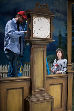
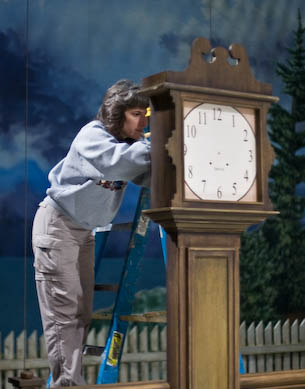 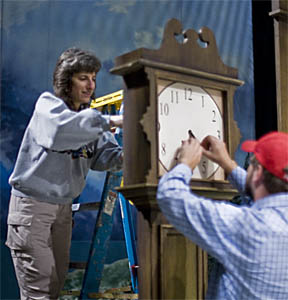
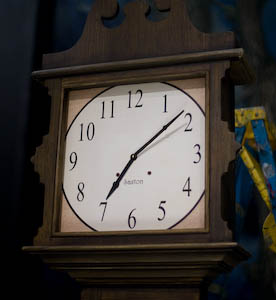
After the clock was installed, we were ready for the final test: checking to see whether it worked correctly with the actual system. The cue would come from the light board instead of the test device, and the signal had to travel over a much longer wire. It worked great! It responded as expected to all the commands it was supposed to handle and didn't react to commands on other channels. It seemed to move consistently, and as we left, the master electrician was experimenting with the different movements and speeds. Later that evening, the crew would work on getting the light board programmed to move the hands the correct amount at the designated time and would work with the directors on selecting an appropriate speed for the motion. We left to go home and catch up on sleep. We didn't hear anything from the theatre after that, and hoped that no news was good news, but did wonder a little whether they had encountered problems and scrapped it. On opening night, we saw the set designer before the show and mentioned our apprehension about whether the clock had continued to perform correctly. He assured us that it had, and we were elated to see it work during the show. Although the clock is only briefly featured in the show, it is the center of attention for those few seconds. Even on our second viewing of the show, I felt a bit nervous wondering if it would perform correctly. I've never been a stage mother before! By my third time, I was able to relax and just enjoy the scene. |
| ©2000-2026 Idle Loop Software Design, LLC. You may not copy or reproduce any content from this site without our consent. |