|
|
FM ScannerHow Cathy hacked a radio...Written by Cathy Saxton We were playing with my parents' FM transmitter for an iPod and had to deal with manually scanning the FM band to find an unused frequency to transmit on. I decided that it would be really convenient to have a device to automatically scan the FM band looking for the frequencies with weak broadcast signals. 
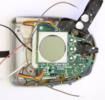
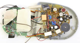
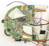
After looking at tuner ICs and finding that I was going to have trouble purchasing just one (I could get 15,000, but that seemed like overkill!) and that they were rather complicated, I decided that a quick and not-too-expensive solution was to hack a radio. A portable digital radio would have buttons for tuning, which I could simulate by sending the right voltage from a microcontroller. So, I could automatically tune stations. Then I'd just need to determine how strong the signal was. A post to the SRS discussion group yielded a solution: Chuck Harrison suggested using the "AGC" (Automatic Gain Control) pin from the tuner IC in the radio. So, step one was to get a radio. Being impatient, I didn't want to wait for a $12 unit from Amazon.com, so I sprung for the $20 radio at the local Target. I got it home and fished it out of its protective plastic packaging. The first thing out was the warranty card with its "Important! Fill this out immediately!" notice. I laughed and immediately voided the warranty by opening the radio. It's amazing how much stuff is packed into the small space! There are two PCBs, each with components on both sides. It's nicely put together for my purposes -- everything's mounted to the case with screws, not flimsy plastic clips. It looked like there was a little unused space near the battery compartment, so I figured I would be able to put my stuff there. Now, I needed to find the tuner IC. There is a lot of tape covering
the components on the boards, so just finding any IC turned out
to take some exploring. But, I found an IC pretty quickly, excitedly
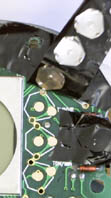
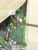
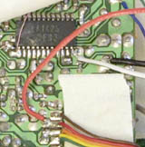
Googled its number/letter markings, and Sure enough, there's a pin labeled "AM-AGC output and FM signal meter output" -- woo hoo! A multimeter confirmed that it does correlate pretty well with signal strength. I explored how the buttons work. The actuator is a concave metal dome, taped down to a PCB with the edges contacting a +V signal. The button is molded into the case, hinged on the side, with a "spike" on the bottom that pushes the top of the dome, flexing the metal to touch a contact point on the PCB. One interesting thing about these buttons is that they are active high; the button inputs I've used previously are high when open, then show a low signal on closure. My original intention had been to take over the radio's controls and just use it for a scanner. But, once I actually had a radio, I decided it was just cruel to destroy it, so I worked on designing an interface that left the radio and all of its controls intact. That meant needing to add my own controls. After considering various strategies, I ended up deciding on a fairly simple user interface that relied on my microcontroller getting power (and thus starting its program) when the radio was turned on, and then using a single button to start the scan, and then to cycle through the weak stations after the scan was complete. I also needed to hook into the tuner buttons without interfering with the radio's buttons; fortunately, the signal lines traced to the bottom of that board, where I was able to add connections.
After taking the above photos, I ended up changing my "power" connection from the red wire (regulated voltage, always on) to the yellow wire (raw voltage, switched on with the radio). For the microcontroller, I chose the SOIC-8 (8-pin surface mount) Atmel ATtiny13-V10 (one of the controllers in the AVR line that I like). It has 6 I/O pins and an analog-to-digital converter (ADC), which is necessary for reading the signal meter. I needed outputs for the up and down tuning, an input for the signal meter, and an input for a button. I used the SOIC (surface mount) version in the radio because of the space constraint. I experimented on a breadboard using the PDIP-8 version of the ATtiny13 connected to the wires from the radio (power, ground, tuning buttons, signal meter). I made sure that I could successfully control the radio and get good readings from the signal meter. I ended up having to use a fairly slow pulse to the tuner buttons; they are obviously designed to react slowly, probably to help debounce the input since it expects that the buttons will be hit manually. I wrote and polished the program in this system, then downloaded it to the SOIC-8, which I then soldered to the radio's wiring. The radio is now back together, sporting the scanner upgrade and a button to control it (in the lower left of the picture at the top of this page). It took about an hour of fiddling with the wires to get it all packed into the case, but it's working great! |
| ©2000-2026 Idle Loop Software Design, LLC. You may not copy or reproduce any content from this site without our consent. |