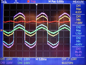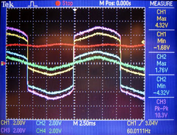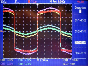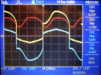
Tom snapped this photo of me while I was taking measurements. My left hand is in my lap; I found that was more convenient than behind my back!
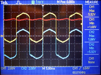
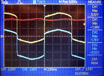
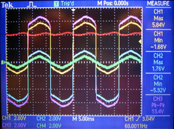
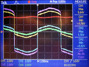
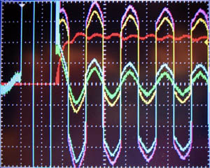
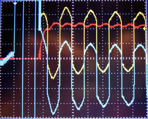
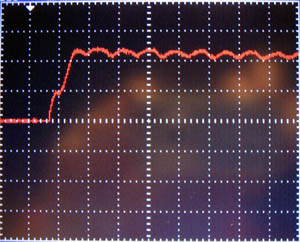
The lights are plugged into house AC, as is the oscilloscope, so the "ground" clips for the probes are not connected. By connecting to the last bulb in the string, I was able to get small values for the measured voltages (relative to the oscilloscope's ground), enabling me to use a scale that also worked well for the waveform showing the difference between V+ and V-.
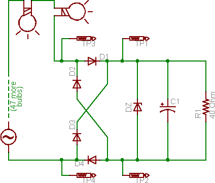
In all cases:
- Vertical scale: 2 V per gridline
- (Horizontal scale: 5 ms / 2.5 ms per gridline,
as specified by column header)
- channel 1 [ch1] (yellow): V+ output from bridge
- channel 2 [ch2] (blue): V- output from bridge
- channel 3 [ch3] (violet): input to bridge (AC)
- channel 4 [ch4] (green): input to bridge (AC)
- math (red): channel 1 - channel 2
(voltage for ornament),
unless otherwise specified
